For the last while I have been working on a weight shift microlight aircraft that will be using a 1200cc BMW motorbike engine to drive the propeller. In the picture below is the injector body and its K&N filter. Its a beast of an engine and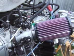 the BMW Engine Control Unit (ECU) has been replaced with a locally manufactured one. Why? The BMW ECU monitors all sorts of sensors on the engine and bike, and if one of these goes faulty then it shuts the engine down- not a great idea in an aircraft. The ECU is good and works well; its simple and fairly easily accessible in terms of being able to connect to it using a laptop. The biggest pain is getting a USB to Serial/RS232 cable and a driver that will work on your operating system, Windows 7 in my case.
By the way, if anyone has had the irritating problem of a jumping cursor as you type when using W7 I have found the cure… dang that problem annoyed me!
I have described the first parts of the electrical and mechanical installation on another site and if you are interested you can see it at http://www.microlighters.co.za/viewtopic.php?f=23&t=12767
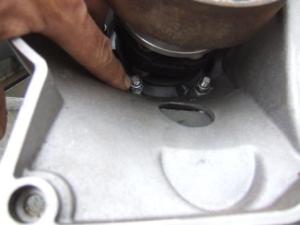
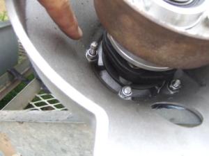
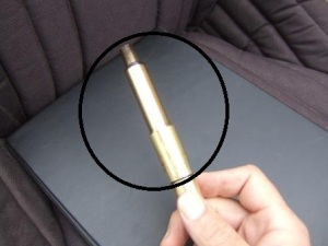
I now have the prop on the aircraft and am getting ready to tune the engine, but there were a couple of chores to perform first. 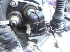 The idle valve apparently (according to Otto, the ECU developer ) jiggles about when you run the engine and thus messes about with the air/fuel mixture, so you need to make sure that it seals properly. You can see the idle valve on the injector housing here. The way that Otto and Frans (Frans Grotepas, who has done a lot of pioneering work on the development of the BMW engine as an aircraft engine) have achieved this is to put a bit of
  nylon pipe around the bit that I have circled on the valve tip, as you can see in the second photo. You then jam this back into the housing and screw it down using the interference between the pipe, valve and housing to create an airtight seal, with any luck.
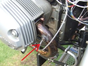
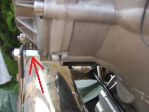
 I also had to move the EGT (Exhaust Gas Temp) sensors to a more sensible place than where they originally were, and seal up the holes where they had been (too far down the exhaust- they need to be 50-75mm from the exhaust outlets on the engine. Whilst fitting the exhaust back on I came across another problem (it never stops!); the exhaust support bracket required that two of the gearbox bolts be extended to allow the bracket to be attached.
After the gearbox had been fixed (from when we last damaged it) the new bolts were not correct. By now I had already fitted the box and of course it needed to come off to access the nuts holding the bolts that I needed to change…. grrr. The bolts that had been used were quite long, see where I am pointing. I got some threaded stainless rod and cut some sections to the length that I needed and then screwed the nyloc nuts onto them (the access is difficult and I am afraid that I said ‘golly’ a few times) and then long nuts onto the outside. The long nuts had been turned down to the correct length to hold the bracket so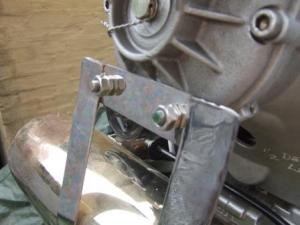 that it did not rub against the gearbox oil drain plug (its never, never simple…). The gearbox was replaced and the exhaust and its bracket fixed in place. The manner in which I have used the half nut and full nut to lock the system may seem strange, but this is in fact the correct way to do it- half nut first.
When all of this was together I got out my compression tester to perform a cylinder compression test. The tester had a male thread, 14mm metric fine (14 x 1.25mm), but the engine spark plugs had a 12mm metric fine thread (12 x 1.25mm)… @#$%^&@!
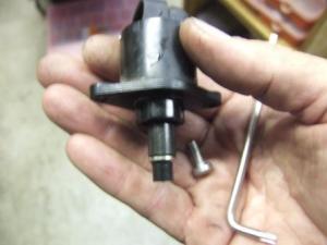
I had to turn and mill up an adaptor…
The compression was measured and may be problematic, with a 12% difference being measured between the cylinders; now my client is asking his BMW connections if this is significant. I think that it may be, so perhaps you’ll get to see a head strip down next.
Jay

